

Ancillary Services Matrix - Stage 2
BACKGROUND
The overarching objective of XFLEX HYDRO project is to develop and demonstrate new technological solutions capable of being integrated in different types of Hydro Power Plants (HPP). These solutions aim to improve hydropower’s efficiency and performance regarding the provision of several Electric Power Systems (EPS) services. Such developments are expected to actively contribute to the decarbonisation of the European EPS, allowing HPP to have increased capabilities for the provision of advanced grid services in face of an evolving EPS characterised by increased shares of time variable renewable energy sources.
The activities developed within the scope of WP2 allowed to perform a detailed assessment of current and emerging flexibility services of EPS and the associated market frameworks for the provision of those services, with a particular emphasis on the countries where XFLEX HYDRO demonstrations are taking place (Portugal, France and Switzerland). In summary, the basket of ancillary services under evaluation (as documented in the Deliverable D2.1) is composed as follows:
- Synchronous inertia;
- Synthetic inertia;
- Fast Frequency Response (FFR);
- Frequency Containment Reserve (FCR);
- Automatic Frequency Restoration Reserve (aFRR);
- Manual Frequency Restoration Reserve (mFRR);
- Replacement Reserve (RR);
- Voltage/reactive power control (Volt/var);
- Black start.
Technologies and demonstrators
The technological solutions under assessment and/or implementation within the scope of the XFLEX HYDRO project are as follows:
- Fixed speed units;
- Variable speed units, through the installation/conversion to Doubly Fed Induction Machine (DFIM) or Full-Size Frequency Converter (FSFC);
- Smart Power Plant Supervisor (SPPS), a methodology to provide an adequate monitoring and extensive knowledge of the machine that will enable the plant owner to manage the risks and costs associated to a temporary off-design operation according to the potential benefits it offers. In this project, SPPS methodology is considered as an umbrella of all the actions, studies and control measures performed to increase the controllability and monitoring of the HPP without the installation of significant hardware;
- Hydraulic Short Circuit (HSC), which allows the hydro power plant (HPP) to operate at the same time a turbine in parallel to a pump. In case of fixed speed units, this enables the simultaneous operation of a pump at constant power and while performing power control with the turbine, varying continuously the consumption of the plant. When variable speed is considered, the operating range of the pump and of the turbine can be combined to further extend the overall operating range;
- Hydro-Battery-Hybrid (HBH), namely the hybridization of the HPP through the installation of a Battery Energy Storage System (BESS).
The breakdown of the technological solutions per demo follows a preliminary rational considering demo owners and associated equipment manufactures view regarding the envisioned development plan for each demo, either in terms of engineering/simulation studies, reduced scale model tests and on-site live tests. For each demo, the set of technological solutions being assessed is as follows (item in bold corresponding to the baseline solution existing in the HPP):
Z'Mutt:
- Fixed speed (baseline – synchronous machine);
- Fixed speed with SPPS;
- Variable speed with a FSFC;
- Variable speed and SPPS.
Frades 2:
- Fixed speed;
- Fixed speed with SPPS;
- Fixed speed with SPPS and HSC;
- Variable speed with a DFIM (baseline);
- Variable speed with SPPS;
- Variable speed, SPPS and HSC.
Grand Maison:
- Fixed speed (baseline);
- Fixed speed, SPPS and HSC.
Alqueva II:
- Fixed speed (baseline);
- Fixed speed with SPPS;
- Fixed speed with SPPS and HSC;
- Variable speed with a FSFC;
- Variable speed with SPPS;
- Variable speed, SPPS and HSC.
Alto Lindoso:
- Fixed speed (baseline);
- Fixed speed and SPPS;
- Variable speed with a FSFC;
- Variable speed and SPPS.
Vogelgrün:
- Fixed speed (baseline);
- Fixed speed, SPPS and HBH;
- Variable speed (FSFC).
In general, the baseline situation corresponds to a fixed speed type electrical machine, being Frades 2 the outlier since this HPP is currently operating with a state-of-the-art Doubly Fed Induction Machine (DFIM) type unit. However, a hypothetical solution based on a fixed speed unit (synchronous machine) was also considered for Frades 2 to be addressed under 1D simulation/engineering studies in order to better understand the expected benefits/limitations of both technological solution for this type of HPP. Regarding the Z’Mutt demonstrator, unit 5 of this HPP is being converted to a variable speed machine (Full-size Frequency Converter (FSFC) type), a parallel development to the XFLEX HYDRO activities. As in the Frades 2 demonstrator, the baseline chosen for Z’Mutt demo is also a fixed speed type unit (synchronous machine).
Methodological approach for assessing the performance of HPP technologies to the basket of ancillary services
The engineering work supporting the assessment of the different HPP technologies with respect to the basket of identified ancillary services relies on 1D SIMSEN simulation models that have been developed and validated in the framework of each project demonstrator initial studies. Afterwards these models, were enhanced to include the model of control system related to both fixed speed and variable speed technologies when applicable. The control structure considered for variable speed technology allows to provide Frequency Containment Reserve (FCR), Synthetic Inertia (SI), Fast Frequency Response (FFR) and automatic Frequency Restauration Reserve (aFRR) ancillary services. The control structure considered for fixed speed includes in principle an active power and speed control loops which are combined with permanent droop enabling to address FCR and aFRR ancillary services. Additionally, for Vogelgrün, the 1D SIMSEN simulation model of the Kaplan turbine and related turbine governor was coupled with a MATLAB model of the Battery Energy Storage System and related HBH joint control using.
The evaluation of the different ancillary services required to select grid codes whenever applicable or to define relevant metrics to quantify the contribution of the demonstrators and related technologies to the different ancillary services. The French Grid Code of RTE has been selected for the evaluation of FCR and aFRR capabilities, while ENTSO-E grid code for Nordic Synchronous Area was considered to evaluate FFR capability. It was assumed that the contribution to aFRR is also representative of the possible contribution to mFRR and RR services. For Voltage/Var control, the magnitude of reactive power that a hydro unit can deliver at maximum active power was considered to represent the contribution to this ancillary service, without need to perform numerical simulations. For black start capability, time domain simulations were performed to quantify the maximum isolated resistive load that could be directly connected to a hydro unit operating at speed no load at 50 Hz, and ensuring that the isolated grid frequency would not fall below 49 Hz when fixed speed technology was considered. When variable speed technology was considered, the full range of speed control was considered for DFIM technology to maximize the contribution to black start, while the limit for FSFC technology was the minimum rotational speed before the unit would stall and result in abrupt shutdown. It is important to mention that variable speed units need to be able to operate in grid forming mode to perform black-start. Moreover, black start capability also requires some external source of energy (battery, auxiliary hydro unit, diesel, etc) and voltage/reactive power regulator shall enable electrical line energization and proper voltage control. All the simulations have been performed under minimum head condition which corresponds to the most detrimental operating condition regarding the provision of ancillary services.
Finally, the evaluation of synchronous and synthetic inertia contributions required a special attention since there is no grid code nor metrics available for these ancillary services. An analytical expression was derived to quantify the magnitude of the active power that a synchronous machine would inject or absorb in case a large power network frequency deviation would occur. This simple analytical expression, which was validated with detailed time domain simulations, enables to show that the magnitude of active power injected or absorbed is proportional to the hydro unit mechanical time constant tm for a given Rate of Change of the frequency (RoCoF). A typical RoCoF value of 1 Hz/s during 1 s was considered to quantify active power injection or absorption. The analytical approach also shows that units operating in turbine or in pump contribute both to synchronous inertia since both feature rotating masses storing angular kinetic energy similarly to a flywheel.
Unlike synchronous machines, the rotational speed of variable speed units is disconnected from the power network frequency. Therefore, inertial response can be emulated by a variable speed unit, using an appropriate control structure to provide the so-called synthetic inertia to the power network. Inertia emulation control structure is based on the swing equation to achieve active power injection or absorption which is also proportional to the RoCoF like for a synchronous machine, and thus replicate the corresponding flywheel effect. Time domain simulations performed enabled to show that variable speed units inject or absorb the same active power as a synchronous machine in case of frequency variation, provided that the power network features enough synchronous inertia so that the variable speed unit can be operated in grid following mode.
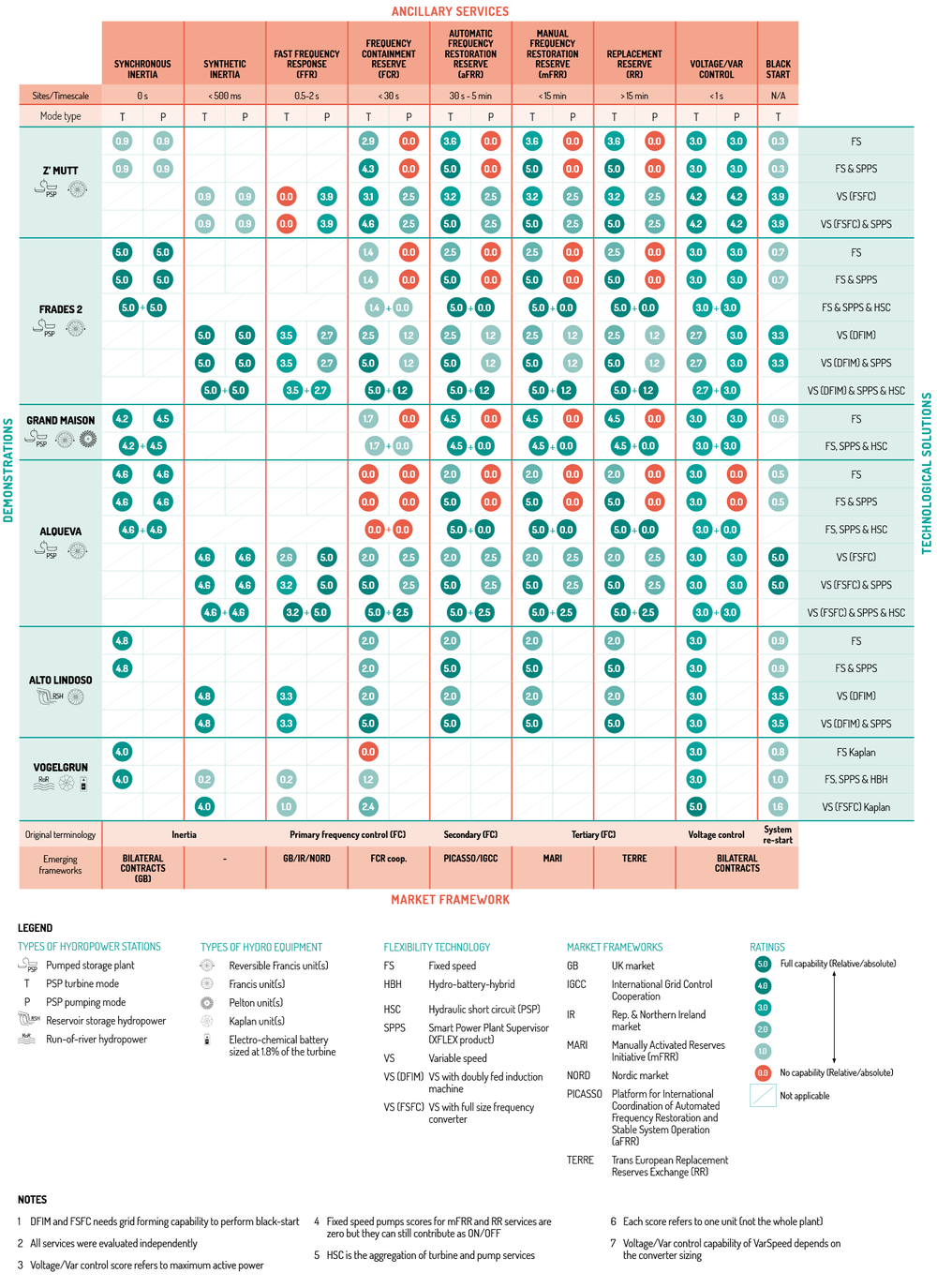
Ancillary Services Matrix (ASM)
The ASM aims to map the different flexibility services, associated flexibility markets, as well as the different technologies options to be integrated in the HPPs to endow them with enhanced capacity to provide the flexibility services. Moreover, the development of the XFLEX HYDRO project is allowing to provide an explicit indication of the level of adequacy of each demonstrator, equipped with a new technological solution, to provide flexibility services. Following this rationale, the complete version of the ASM is now presented.
The systematic numerical simulation and analytical approaches of ancillary service contribution of each demonstrator and related technologies enabled to produce a scoring system between 0 (no capability) and 5 (full capability) that has been introduced for each ancillary service, allowing to populate with the corresponding scores the Ancillary Service Matrix, presented below.
In this matrix, each score refers to the service capability of one unit, not the whole power plant. The magnitude of the services which can be delivered at the plant level is the sum of all the individual units contributing to a given service at the same time. This is also applicable to the HSC operation, where the power plant contribution corresponds to the aggregation of turbine and pump services. In addition, it should be mentioned that all services were evaluated independently, nevertheless power plant operators can provide a combination of some grid services at the same time, provided that the units have sufficient provision from capacity perspectives, and thus it is subject to an economical optimisation from the electricity market perspective.
What are the key messages from the ASM?
The scoring presented in the ASM with respect to the different demos/technologies and evaluated ancillary services provides relevant conclusions:
• For Alqueva II and Vogelgrün, the use of variable speed enables to provide FCR service and overcome the adverse power response of fixed speed technology, due to water way dynamics.
• With variables speed technology, the contribution to FFR is strongly influenced by the rotating inertia of the unit in turbine mode and larger mechanical time constant enable higher FFR contribution; surprisingly, this is not applicable in pump mode where the rotating inertia has no influence on the ability to provide FFR service.
• Synthetic inertia is equivalent to synchronous inertia in terms of ability to inject or absorb active power in the power network in case of grid frequency variation provided the power network already include sufficient synchronous inertia.
• Variable speed technology enables to increase black-start capability by a factor ranging between 2 and 10 as compared to fixed speed technology, provided that the variable speed control encompasses grid forming capability.
• HSC enables fixed speed power plants to provide FCR and aFRR services as well as adjustable mFRR and RR services, when operating in pump mode, with a power range corresponding to the turbine power range.
• SPPS enables to take advantage of the full turbine power range between 0 and 100% of rated power to provide aFRR, mFRR and RR services with typical extension from 40% to 100% of the power range.
• HBH enables the Vogelgrün demonstrator to overcome the adverse power response due to waterway dynamics and to contribute to FCR while reducing the associated wear and tear.
XFLEX HYDRO TECHNOLOGY MODELS’ DOCUMENTATION
LEARN MORE